Kansas City
Subdivision

Signals on the Kansas City Subdivision
Updated 1 October 2008
Definitions
Some definitions (from the Consolidated Code of Operating Rules, 1980 revision)
Before starting to design a signal system, it is worthwhile to review the definitions from the
Operating Rules of the North American prototype.
For me, that is The Milwaukee Road in the 1970s.
Railroads need to have precise definitions so that the interpretation of the rules will result in safe operation.
If there is any chance of rules being interpreted more than one way,
the rules have to be updated.
Since Railroads also need Signals to work with their already established timetable and train order operation,
notice the definition of CTC below. CTC has signals supercede train authority.
The whole idea of a signal system is to authorize train movement safely and to expedite the movement of trains.
I realize these definitions may seem a little dry, but they are necessary to the proper implementation of a signal system.
- Block - A length of track of defined limits, the use of which by trains and engines is governed by block signals, cab signals or both.
The Block is the basic unit of track that a train may occupy. Blocks could be long or short, depending on the traffic density and other factors. If a railroad had a high traffic density, then they could put in more blocks. It helps to think of it this way - 1 train per block can run at maximum speed; two trains in a block means that the following train will have to move at a restricted speed. So, more blocks = more trains that can run at speed in a section of railroad.
- Block Signal - A fixed signal at the entrance of a block to govern trains and engines entering and using that block.
This is just the general definition of the signal that controls entrance to a block. Later on we will come to different types of signal.
- Absolute Signal - A block or interlocking signal designated by an 'A' marker or by the absence of a number plate.
- Interlocking Signals - The fixed signals of an interlocking.
- Interlocking Limits - The tracks between the outer opposing absolute signals of an interlocking.
- Interlocking - An arrangement of signals and signal appliances so interconnected that their movements must succeed each other in proper sequence and for which interlocking rules are in effect. It may be operated manually or automatically.
- Manual Interlocking - An interlocking operated by an employee by means of an interlocking machine.
- Centralized Traffic Control System (CTC) - A block signal system under which train or engine movements are authorized by block signals whose indications supersede the superiority of trains for both opposing and following movements on the same track.
See how all the definitions come together here? You have blocks and signals controlling all train movements.
- Control Operator - An employee assigned to operate a CTC or interlocking control machine.
- Signal Aspect - The appearance of a fixed signal conveying an indication as viewed from the direction of an approaching train; or the appearance of a cab signal conveying and indication as viewed by an observer in the cab.
- Signal Indication - The information conveyed by the aspect of the signal.
What the system needed to do
Where I have put information in parenthesis (), it refers to the definitions given previously.
- Detect Train locations (Blocks). I decided that I would need to be able to determine where trains were located on the layout,
so I needed some kind of system to detect trains sitting on track. Refer to the Block definition.
- Control turnouts (Interlocking). I needed to be able to remote control turnouts as this is a basic requirement
of interlocking plant on railroads.
- Control signals (Interlocking Signals) The dispatcher needs to be able to request that a signal is cleared.
- Lock turnouts when signals are cleared over them and when trains are on the turnouts (Interlocking). It's no good giving a train a clear signal when someone else can change the turnout under the train.
- Prevent unsafe signals to be displayed (Interlocking). The system should perform all of the checks to ensure that the signal is safe to clear.
- Show train location on a control panel (CTC Manual Interlocking). The dispatcher needed to be able to see at a glance where trains are located on the track so they can check on movements and see when it is clear to authorize another movement.
- Show Signal status on a control panel (CTC Manual Interlocking). When the dispatcher/operator requests a signal be either put to stop or cleared, they need to see if their request was granted. When trains pass by signals, the signals should then display stop and this should also be reflected on the control panel.
- Show Turnout status on a control panel (CTC Manual Interlocking). When the dispatcher wants to change a turnout, they will need to see if it is locked and whether it is lined correctly.
- Read signal lever position on control panel (CTC/Manual Interlocking). This is how the dispatcher will request that a signal is cleared. Note that the dispatcher does not have direct control over the exact signal indication, but rather they request that the signal shows a 'proceed' indication.
- Read turnout lever positions on control panel (CTC/Manual Interlocking). This is how the dispatcher changes the turnouts on the layout.
- Show 'direction of traffic' indicators on control panel (CTC). This perhaps the most complex requirement in that the system needs to keep track of the direction the block was signaled for when the train entered the block. This is done so that an opposing train cannot get a clear signal to proceed against the first train.
Design for each requirement
- Detect Train Locations. I chose current sensing detectors and divided the railroad into electrical blocks. The detector outputs are connected to SMINI board inputs. The current sensing detectors can detect as little as 1 milliamp of current flow between the rails. For locomotives, this is easy. For rolling stock, I had to make resistor wheelsets so that each and every piece of rolling stock could be detected. If you leave a boxcar sitting by itself on my main track, the panel will show the block as occupied. Even after you turn the system power off and back on again. This arrangement would use one input pin per block. The layout was divided into 9 blocks in total. A larger layout would require many more blocks. I selected Bruce Chubbs DCCOD (DCC Optimized Detector). This is a good design as it isolates the DCC track power from your signal electronics. It is very sensitive and very accurate. I was able to build 10 of these for a unit cost of $15.00
- Control Turnouts. I chose to use 2 output pins from the SMINI to control the tortoise switch machines. The circuit for this control is found in the C/MRI User Manual.
- Control Signal LEDs. I chose to use 2 output pins from the SMINI to control each bi-colour LED that is used on the layout. Some signals have 3 LEDs, others have 2 LEDs and some have just 1 LED. The circuit for this control is found in the C/MRI User Manual.
- Lock Turnouts. I chose to use a software program to control turnout locking. This is where the C/MRI system really begins to shine. You give all of your equipment meaningful names and then you can write simple program statements to control these. I designed this so that a turnout within an occupied block would be locked. The turnout is also locked if there is a signal cleared across the turnout.
- Use computer software logic
- Use output from SMINI board to control LEDs on control panel.
- Use output from SMINI board to control signal indicator LEDs on control panel.
- Use outputs from SMINI board to control turnout indicator LEDs on control panel.
- Use inputs from SMINI board to read switch positions on control panel.
- Use inputs from SMINI board to read switch positions on control panel.
- Use outputs from SMINI board to control direction of traffic LEDs on control panel.
Design for the Control Panel
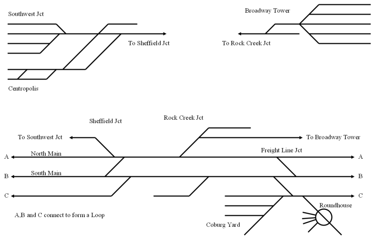
I began by converting the layout plan into a schematic diagram. Here is the layout plan.
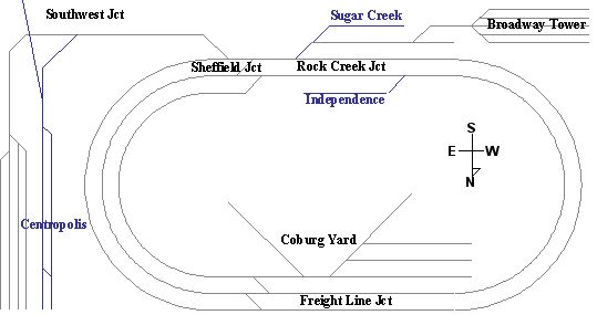
Taking a cut out of the loop on the left hand side and straightening out the track yields the following schematic

Southwest Junction and Broadway Tower are staging areas and are not signaled. Centropolis is an industrial switching district and is not signaled.
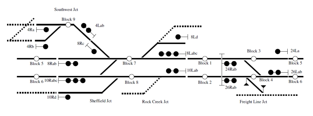
The next step is to decide where signals should go. The results are below:-
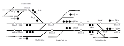
Blocks
The tracks with dotted lines are uncontrolled track. There is no block detection in these areas. Each white circle represents a block. The block extends from one line break to the next line break.
Signals
The black circles represent signal heads. Where a signal faces to the right,
it means that a train approaching from the left of the signal will see the signal.
Likewise, when a train is moving from right to left, the train will observe all of the signals that point to the left.
A signal protects the entrance of each block. For example, a train travelling from Southwest Junction
(top left of the diagram) will encounter Signal 4R first, then Signal 8R, then Signal 24R.
A train travelling from Broadway Tower (top right of diagram) will encounter Signal 8L first, and then Signal 24L.
All signals have left and right positions. The rule is all trains travelling from Left to Right will be governed by Right signals.
Trains travelling from Right to Left will be governed by Left signals.
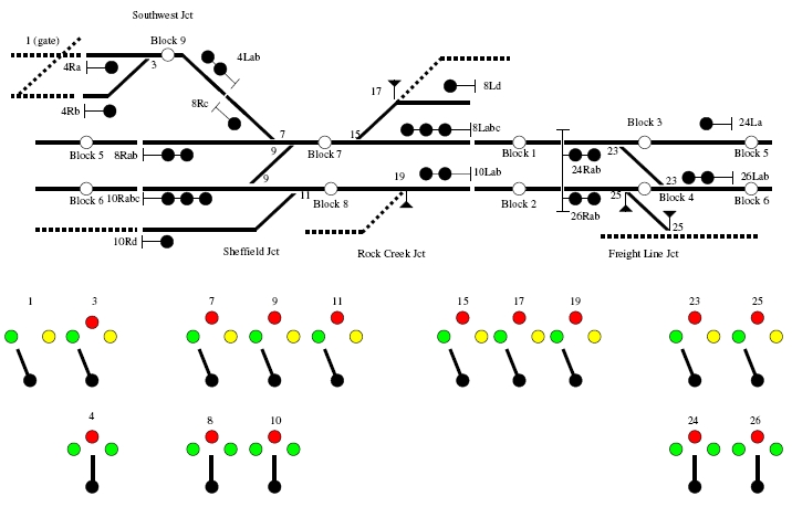
Turnouts
Each turnout is labeled with an odd number. Some turnouts are crossovers and comprise both turnouts in the crossover.
The Normal position of the turnout is the unbroken line, and the Reverse position of the turnout is the broken line.
Now there is enough information to describe the movement of a train from Broadway Tower to Freight Line Junction
on the North Main (refer to the schematic, this is the top of the two main tracks.).
- First, Turnout 15 must be in the Reverse position. Turnout 9 and 7 must be in the Normal Position.
- There must not be a train in Block 7 on turnouts 7, 9 and 15.
- There must not be a train in the next block (Block 5).
- Finally, Signal 8L will be cleared (shows green).
This will allow the train to proceed to Freight Line Junction where they will probably stop at signal 24L.
Using the Panel Levers, the operator would set Turnout 7 and 9 to Normal and Turnout 15 to Reverse.
After the Turnouts complete their movement (remember these are electric motor style turnouts and can take up to 10 seconds to complete their traverse),
the Operator would use the Signal Lever for Signal 8 and set it to the L position.
If all the conditions for a safe signal are present, then Signal 8L will show green.
The Turnouts will then be locked so they cannot move while a train is moving over them.
The Turnouts will stay locked until the train leaves the block on the turnouts.
Full signal diagram.

This shows the arrangement of the levers.
The top row are the turnout levers and the bottom row are the signal levers.
The normal position of the turnouts is the lever set to the left, while the reverse is the lever set to the right. The normal position of the signal levers is straight up at stop. To clear a right signal, the lever is moved to the right. Likewise to clear a left signal, the lever is moved to the left. You can see that it is not possible to clear two opposing trains into the same block that is protected by opposing signals on the same lever as the lever can only be left or right, not both. Other checks are made to ensure that no other signals oppose the movement. I will provide more detail on that when we come to the logic design.
The circles above the levers are indicator LEDs which confirm the lever input.
If you give a right signal and it is not safe to do so, the indicator will not change.
So the indicators are feedback to the operator which confirm the operator's input.
The middle indicators above the turnout levers are lock indicators and they show that the turnout is locked from moving.
The turnout could be locked because there is a signal cleared across it or a train is standing on the turnout.
In either case it is not safe to move the turnout, so the system locks it.
The operator can move the lever, but no action will take place.
Previous - Research Next - Logic