Kansas City
Subdivision

Signals on the Kansas City Subdivision
Updated 1 October 2008
The beginning
There was no doubt about it, I wanted working signals on my model railroad. Where to start? What to do? Many questions presented themselves.
So I began a brainstorming phase where I thought about the kind of signals that I wanted.
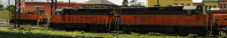
Turn back the clock about 26 years - I was working for the Milwaukee Road in Kansas City, as one of the tower operators at West Wye Tower.
West Wye Tower controlled a double-track wye connecting the Milwaukee Road, Kansas City Southern and Rock Island
(soon to become the Chicago and Northwestern).
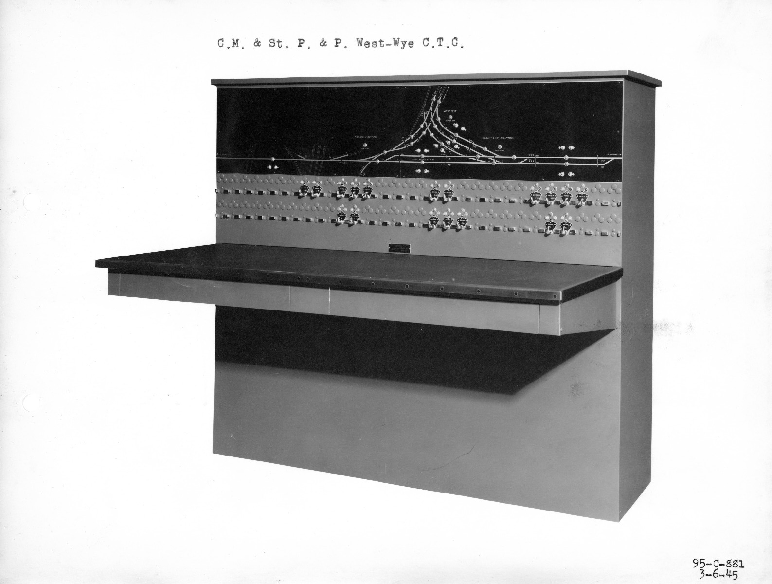
West Wye Tower contained a Union Switch & Signal 'Direct Wire' control machine.

The machine lasted into the 1990's when it was decommissioned and replaced by remote control between the Drawbridge operator
and the Kansas City Terminal control operator. Until that time, it directly controlled the junction.
The system I designed incorporates similar functionality to the US&S machine.
How did the US&S machine work?
There is a track diagram, with red lamps that illuminate when a train is 'in the circuit', two rows of little 'lever' switches with coloured
lamps over them. Behind the levers were pie wedge shaped plates with numbers.
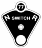
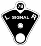
The number on the plate designated which switch or signal was controlled by that lever.
These levers operated the corresponding switch or signal immediately if it was safe to do so.
For example, clearing a Milwaukee train out of town over the Drawbridge.
- The operator would first rotate the switch lever for switch 35 to the 'R' for reverse position.
- There would be a short delay of 1-2 minutes while the switch machine moved the turnout to the reverse position.
- Then the yellow R light would illuminate, telling the operator that the turnout was lined and locked for the diverging route.
- Then the operator would rotate signal 36 lever to the 'R' position (for Right Signal).
- If it was safe to clear the signal, then the lock light (red lamp over switch plate) for switch 35 would illuminate,
the red lamp over signal plate 36 would extinguish and the green lamp over 36R would illuminate.
This was feedback for the operator, to tell them that 36R was clear and that the train could move up to Freight Line Junction.
While signal 36R was cleared or there was a train standing on the track, switch 35 would remain locked.
Any movements of the lever for switch 35 would be ignored by the machine.
- Next, the operator would set the lever for switch 53 to the 'R' position to reverse the turnout.
- After 53 indicated 'R', then the operator could clear Signal 52R by moving the lever for signal 54 to the 'R' position.
- When the train passed signal 36R, the track circuit light would illuminate and signal 36R would 'drop' to stop.
- This would be shown on the panel by the red lamp illuminating and the green lamp extinguishing.
The signal could not be cleared, nor would changing the signal lever have any effect while a train was 'in circuit'.
The West Wye interlocking machine worked differently to a CTC machine.
CTC machines sent out a coded message on the communications line to remote locations.
The remote control point worked out the logic of the request and sent back confirmation (via coded message) to the CTC control panel.
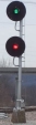 Prototype Signal
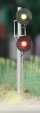 Model Signal
The signals used at West Wye Tower, and all of the Milwaukee Road mainline up to Laredo Missouri were
Union Switch & Signal H Dwarf signals and H series Searchlight signals.
System Requirements
The system needed to:-
- Control turnouts with Tortoise switch machines.
- Perform block detection.
- Control signals on the layout.
- Display the current state of turnouts, signals and blocks on a CTC panel.
- The layout should be controlled by means of switches on the CTC panel.
- The logic behind the CTC panel had to perform all of the checks necessary to allow trains to proceed safely.
- It should not be possible to allow a train to proceed if there was another train approaching or in front of the train.
- Turnouts could only be changed when there was no signal cleared and no train standing on them.
The first stop on the research trail was Mike Burgett's CTC web site.
Unfortunately, this site is currently under reconstruction.
This is an excellent reference for anyone wishing to research a Signal System.
On this web site you can learn about CTC Signalling and find links to other web sites about system hardware, signals and software.
Design considerations
I considered a few other possibilities, such as:-
- Automatic signaling.
- Computer aided dispatching (having the control panel on the computer instead of a real CTC panel).
- Other control systems.
- Designing my own system from scratch.
I investigated some of the commercial signal system offerings.
Signal Components and Systems Investigation
Atlas signal system
( http://www.atlasrr.com/trackmisc/hosignals.htm) -
This product was announced in 2006 and provides realistic signaling.
I found that the Atlas offering was good if you wanted simple block signals,
however I needed more realism and control since my track plan consisted of more complex junctions
than the Atlas system could cater for.
The Atlas signals also were not applicable to my prototype. They would serve NYC modelers well.
The Rock Island also had this style (Type G) signals on the line from Polo, Missouri to Des Moines, Iowa.
Digitrax Signal System
(http://www.digitrax.com/menu_detectionsignaling.php) -
The Digitrax offering had been around for a while and looks very good.
The drawbacks for me were that they only offer colour light signals and not searchlight.
I spent a lot of time reading all of the Digitrax documentation and concluded that it was a good flexible system,
however I would need to use LocoNet to hook it all together and there did not seem to be an easy way to use other products
in conjunction with the Digitrax system.
TracTronics Components
((http://users.rcn.com/weyand/tractronics/ttinchom.htm) -
TracTronics offers circuit boards and designs to implement signaling, but this also was very 'homebrew' and did not look like a full integrated system.
This would be great for 'do-it-yourself' approach where you would like to save a few dollars.
JLC Enterprises C/MRI
(http://jlcenterprises.net) - I had not heard of this product before the series of signaling articles appeared in Model Railroader magazine,
starting with the January 2004 issue. C/MRI stands for Computer / Model Railroad Interface.
This system was designed by Dr. Bruce Chubb, MMR. It was designed many years ago and has matured into a very flexible system.
C/MRI is made up of various components, particularly Nodes which can have many connections on them.
These connections can control switch machines, signals and they can read the state of turnouts and blocks using different sensors.
This system offers the greatest flexibilty and is easy to change through programming.
Once you have wired it up, you do not need to re-wire if you need to change the logic.
Next - Design
 Prototype Signal
 Model Signal