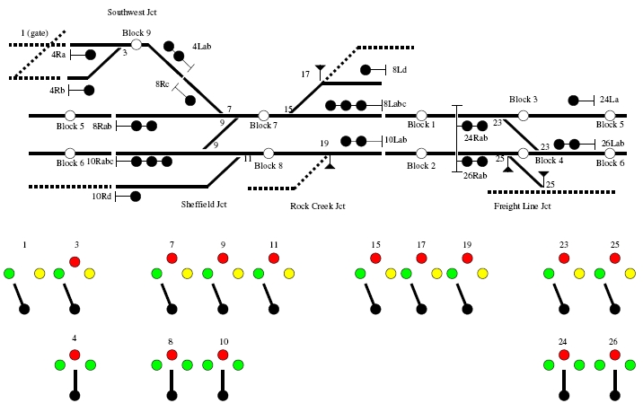

I have included the diagram of the control panel for reference when you read along with the article.
All that is required in my program is to specify which node I want to use, then call the C/MRI library routine.
All of the devices have meaningful names. These names are called 'variables' in programming terminology. It is easiest to think of a 'variable' as a place in the computers memory to store a bit of information. We can put something into a variable and we can read something out of the variable later. Since variables are part of the computer's memory, their values are lost when the program finishes.
All of my variables are set by inputs from the railroad (SMINI nodes) and by the program logic, so it doesn't matter that the variables 'disappear' when the program finishes.
Example:-
  If Block3 = OCC Then
    Signal24Right = Stop
    Signal24Left = Stop
    Turnout23Lock = Locked
    BlockIndicator3 = On
  End If
In English, If block 3 is occupied, then make signal 24 left and right show 'stop' and lock turnout 23 so it cannot move.
My code is a little more compact than the above. Here is how we set the turnout lock on number 3.
SwitchLockIndicator3 = Abs(Block9 Or (SignalIndicator4 <> SignalIndicatorStop))
This is simply short cut code for:-
IF Block9 = OCC OR
  SignalIndicator4 <> SignalIndicatorStop THEN
    SwitchLockIndicator3 = Locked
ELSE
  SwitchLockIndicator3 = Unlocked
END IF
In English again, if block 9 is occupied or signal 4 is not at stop then lock turnout 3.
     ' Turnout 3, protected by signal 4 and block 9
     ' Ignore switch lever input unless it has changed.
     If SwitchLeverInput3 <> SwitchLeverState3 Then
       SwitchLeverState3 = SwitchLeverInput3
       ' Switch Lock logic taken care of by TurnoutLockCheck
       If SwitchLockIndicator3 = 0 Then
           Turnout3InTransit = Timer
           If SwitchLeverState3 = SWN Then TurnoutOutput3 = TUN
           If SwitchLeverState3 = SWR Then TurnoutOutput3 = TUR
       End If
     End If
Since I model an interlocking machine, it is possible that the operator has changed the lever position when it is not allowed to change.
So the first part ignores the input unless it has changed. To do this, you need two variables, one to keep track of the Input
and one to keep track of the last state of the input. The Input (SwitchLeverInput3) is set by reading the SMINI node
that the panel switch is connected to. The State (SwitchLeverState3) is set by the program.
So, if the lever is in a different position than it was last time we checked, then we need to do a further check to see if we have to change the turnout position. We then make the State the same as the Input (so we can check the State next time around - remember this code is executed every .001 seconds forever).
The next part says 'If the turnout is NOT locked, then change its position.' If SwitchLockIndicator3 = 0 (if it is not locked) Then Set the position. This is accomplished by looking at the SwitchLeverState.
If the state is 'SWN' (which is Normal), then the TurnoutOuput is set to 'TUN' (which is Normal). If the state is 'SWR' (which is Reverse), then the TurnoutOuput is set to 'TUR' (which is Reverse).
So we only change the turnout when it is safe to do so. The lines beginning with apostrophes (') are comments and are there to remind me what the code does.
Another feature that I chose to implement is 'Running Time'. This is a feature of signal systems that helps to prevent problems when the operator has cleared a signal and needs to put the signal back to stop in the face of an approaching train.
Before the operator can change turnouts or clear a different signal, they must wait for 5 minutes before the plant 'unlocks'.
Here is the code for Signal 4.
     If Signal4RunTime = 0 Then
       If SignalLeverInput4 <> SignalLeverState4 Then
         ' if signal was dropped by operator, then begin running time.
         If SignalLeverState4 <> SignalLeverStop _
           And SignalIndicator4 <> SignalIndicatorStop Then
           Signal4RunTime = Timer
         End If
         SignalLeverState4 = SignalLeverInput4
         If SignalLeverState4 = SignalLeverStop Then
           SignalIndicator4 = SignalIndicatorStop ' put Signal 4 to stop
         Else
           If SignalLeverState4 = SignalLeverLeft Then
             Signal4LeftLogic
           Else
             Signal4RightLogic
           End If
         End If
       End If
     Else
       SignalLeverState4 = SignalLeverInput4
     End If
Lets take a look at the outermost IF statement.
   If Signal4RunTime = 0 Then
   	code
   Else
      SignalLeverState4 = SignalLeverInput4
   End if
This is a check for 'Running Time'. A value greater than zero means that the signal is locked from being changed.
If it is running time, then we just record the lever state. If it is not running time, then we will perform the rest of the checks.
Now lets look at the code inside the first IF statement.
If SignalLeverInput4 <> SignalLeverState4 Then(This is the same as the turnout lever check earlier) We will only perform this code if the operator has actually changed the lever.
The next part checks to see if the operator has put the signal to stop and starts the running time timer. I use the built in timer function in Visual Basic. There is another part of the program which checks the timer to see if the time limit has expired - I have it configured for 30 seconds.
Next we record the lever input state (SignalLeverState4 = SignalLeverInput4) If the signal lever is at stop, then we put the signal indicator to stop. Other code reads the signal indicator to decide what to display on the signal on the railroad. If the signal lever is anywhere else but stop, then check if it is Left or Right.
In order to make this code more readable, I have the logic for each Left and Right signal in its own routine. These are the Signal4LeftLogic and Signal4RightLogic routines. When the operator requests the Left signal to be cleared, this is the logic that is performed:-
   Sub Signal4LeftLogic()
      If Block9 = CLR Then
       	SignalIndicator4 = SignalIndicatorLeft
     	End If
   End Sub
This is pretty straight-forward, if the block that the signal protects is clear, then go ahead and set it to Left. Other code will actually set the signal head based on the SignalIndicator4 and the turnout position. The code for the Right signal is more involved, as we should check block 9 and if there is a signal already cleared in the opposite direction.
   Sub Signal4RightLogic()
     ' can clear if block9 is clear
     If Block9 = CLR Then
       ' if turnout 7 is normal, then okay to clear right
       If TurnoutIndicator7 = TurnoutIndicatorNormal Then
         SignalIndicator4 = SignalIndicatorRight
       Else
         ' turnout 7 is reverse, check if signal 8 is left (against 4)
         If SignalIndicator8 <> SignalIndicatorLeft Then
           SignalIndicator4 = SignalIndicatorRight
         End If
       End If
     End If
   End Sub
First, only clear the signal if block 9 is clear. If turnout 7 is normal then there can't be a conflicting signal cleared
(If signal 8 Left is cleared, it won't conflict because the train for signal 8 left will be going 'straight' through
turnout 7 and turnout 7 is protected by signal 8 Right.) So it's okay to clear, again setting the SignalIndicator4.
However, if Turnout 7 is reversed, then we have to check if signal 8 has been cleared left. This could cause a collision! Only if Signal 8 Left is not cleared (SignalIndicator8 is not equal to SignalIndicatorLeft), can we clear Signal 4 Right.
We can see on the diagram that there are 4 signal heads in Signal 4. These are 4Ra (Signal 4 Right A), 4Rb (Signal 4 Right B), 4Lab (Signal 4 Left A and B). These designations are also a Union Switch and Signal standard that I chose to adopt. Notice that the Signal 10 Right has 4 heads (10Rabc 10Rd).
Once we have determined that it is safe to give a proceed signal, we then need to decide what indication we will show. Again, I have defined symbolic names for the numbers that will make the signals the right colour. The information on how to do this is in the C/MRI users manual.
The routine is Signal4HeadLogic, which looks like this:-
   Sub Signal4HeadLogic()
     ' Signal 4 Left Head logic
     ' A (GRNRED) if turnout 3 is normal
     ' B (REDYEL) if turnout 3 is reverse
     If SignalIndicator4 = SignalIndicatorLeft Then
       If TurnoutIndicator3 = TurnoutIndicatorNormal Then
         Signal4LeftHead = GRNRED
       Else
         Signal4LeftHead = REDGRN
       End If
     Else
       Signal4LeftHead = REDRED
     End If
     ' Signal 4 Right Head logic
     ' A = turnout 3 normal
     ' B = turnout 3 reverse
     If SignalIndicator4 = SignalIndicatorRight Then
       If TurnoutIndicator3 = TurnoutIndicatorNormal Then
         Signal4RightHeadA = GRN
         Signal4RightHeadB = RED
       Else
         Signal4RightHeadA = RED
         Signal4RightHeadB = GRN
       End If
     Else
       Signal4RightHeadA = RED
       Signal4RightHeadB = RED
     End If
   End Sub
This is not too difficult to understand. First we check for the Left head. If the Signal Indicator for 4 is set to Left then
we will check the turnout next.
The time between the operator moving the lever and the panel lamp coming on to confirm the lever input is less that 1/10 of a second. The most important thing that has been done is to give every part of the system a sensible name so that the code is easy to read and understand.
If you would like assistance, further information or a live demonstration of my system, please contact me on kelly.loyd at internode.on.net